|

Solving IK and FK for any type of mechanism
The Inverse Kinematics (IK) or Forward Kinematics (FK) are solved for a mechanism by using IK Groups and IK Elements (see the section on basics on IK groups and IK elements). Keep following points in mind in order to successfully set up IK or FK calculations:
Specify individual kinematic chains by providing a base and a tip.
Specify a target to follow.
Group IK elements in a single IK Group if they share common joints.
Sort individual IK Groups in order to obtain the wanted behavior.
Verify that joints in a kinematic chain have the correct properties enabled or disabled.
Verify that individual IK Elements are not overconstrained. If this cannot be avoided, then select a damped resolution method.
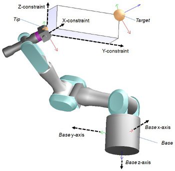
The last point is quite important to understand: a kinematic chain's tip that has all constraints turned on, will follow its associated target in the x-, y-, z-directions, while trying to keep the same orientation as the target. This however only works well when the kinematic chain has at least 6 non-redundant Degrees of Freedom (DoFs). The tip should always be appropriately constrained (i.e. never indicate more constraints than there are DoFs in the mechanism). Positional constraints are most of the time specified relative to the base's orientation as can be seen from following figure:

[Positional constraints for a kinematic chain]
Sometimes it is however not possible to correctly specify the constraints for a tip, and in that case the IK group's calculation method should be a damped method (e.g. the damped least squares method) with an appropriately selected damping factor. A damped resolution method should also be selected when a target can't possibly be reached (out of reach, or close to a singular configuration). Damping can result in more stable calculations, but keep in mind that damping will always slow down calculations (more iterations will be needed to bring the tip into place).
Turning Alpha-Beta constraint on, will match the tip's z-axis orientation with the target's z-axis orientation, while keeping a free rotation around the z-axis if Gamma constraint is off. When Alpha-Beta constraint AND Gamma constraint are turned on, then the tip will try to adopt exactly the same orientation as its target.
Solving the IK problem for simple kinematic chains is explained in the section on basics on IK groups and IK elements. Solving the FK problem of simple kinematic chains is trivial (just apply the desired joint values to all joints in the chain to obtain the position and orientation of the tip or end effector). It is less trivial to solve the IK and FK problem for closed mechanisms.
Solving IK and FK for closed mechanisms
In following section, two general examples are discussed that should allow the user to understand the approach to solving general type closed mechanisms:
In the case of an FK problem, identify first the joints that you want to control (i.e. the joints that are driving the mechanism, the active joints). Those joints should be excluded from all kinematic calculation (select a joint mode different from inverse kinematics mode). Those joints will be considered as rigid by the kinematic calculations from now on. Then, identify which kinematic chain needs to be closed. Closing will be handled by loop closure constraints in the form of tip-target pairs as shown in following figure:

[Forward Kinematics solving method for closed mechanisms]
Then, set the desired joint values for the active joints and call the inverse kinematics functionality to handle loop closure constraints.
Following example shows some additional functionality that can be used to solve complicated kinematic problems:

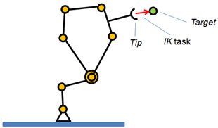
[Inverse kinematics task]
As can be seen from the figure, there is one IK task desired by the user: bring the tip onto the target (or have the tip follow the target). This can be solved in the regular way, or the user can make usage of the joint dependency functionality. Following figure demonstrates this:

[Inverse kinematics task with joint overlap constraints]
The IK main task is in charge of reaching the target, the loop closure constraint is in charge of closing the mechanism, and the joint overlap constraints are in charge of keeping the base of the mechanism overlapped (as one single chain). The parameters of the joint dependency linear equation have to be carefully chosen in order to reach a perfect overlap (e.g. if two corresponding joints (the ones linked through the overlap constraint) have the same orientation, then the coefficient in the equation needs to be set to -1 (since one joint is built bottom-up and the other one is built top-down)).
Most of the time there are several different ways of solving the IK or FK of a mechanism, and it is always worth considering various alternatives before implementing the most complicated one.
|